I. Core Value of Temperature Control Accuracy: Lay a Solid Foundation for Reliable Test Data
In the field of environmental reliability testing, temperature control accuracy is the core key determining the repeatability and reliability of test data, and it is also an important prerequisite for ensuring the scientificity of product R&D and quality inspection. It is specifically reflected in the following two aspects:
• Core Demand of Strict Industries: In high-end industries such as military, electronics, and aerospace, product performance is extremely sensitive to temperature changes. Even a small temperature deviation may lead to serious distortion of test results, which in turn misleads R&D directions and increases production costs. High-precision temperature control is a rigid demand for such industries.
• Performance Advantages of Lab Companion: Lab Companion's high and low temperature rapid temperature change chamber, with the core indicators of ±0.5℃ temperature control accuracy, ±0.1℃ temperature fluctuation, and ±2℃ temperature uniformity, greatly exceeds the industry average standard. It can fully ensure the accuracy and authority of test data, adapt to various high-end and harsh scenarios, and provide solid support for enterprise R&D and quality inspection.
II. Lab Companion Temperature Control System: Triple Collaboration to Unlock the Code of Precision Regulation
The excellent temperature control effect of Lab Companion's high and low temperature rapid temperature change chamber stems from the triple collaborative linkage of high-precision temperature sensors, intelligent controllers and high-efficiency heaters, constructing a full-process precision temperature control system. The functions of each component are as follows:
• High-precision Imported Platinum Resistance Sensor: With an accuracy of up to ±0.1℃, it has the advantages of fast response speed and strong anti-interference ability. It can collect temperature data of each area in the chamber in real time and without deviation, providing reliable data support for precise regulation.
• PLC Integrated Fuzzy Control Algorithm (PID + Fuzzy Control): Integrating the stability of traditional PID control and the flexibility of fuzzy control, it can quickly compare real-time temperature with preset parameters, dynamically adjust the output power of refrigeration and heating, realize millisecond-level precise regulation, and avoid temperature overshoot and lag.
• Multi-section Stainless Steel High-efficiency Heater: Through scientific structural design, it is installed in the air duct and avoids the refrigeration evaporator to eliminate functional interference. It can dynamically match the heating power, with uniform heating and no local overheating, ensuring that the temperature reaches the set value quickly and remains stable for a long time.
III. Analysis of Precision Parameters: Every Indicator Empowers Reliable Testing
All precision parameters of Lab Companion's high and low temperature rapid temperature change chamber have undergone multiple rounds of strict testing and professional calibration, ensuring stable compliance during long-term operation. The core functions of each parameter are as follows:
• Temperature Control Accuracy ±0.5℃: Ensure that the temperature in the chamber is stably maintained within the range of ±0.5℃ of the set value for a long time, avoid test errors caused by temperature deviation from the source, and ensure the consistency of test results.
• Temperature Fluctuation ±0.1℃: Effectively suppress small temperature fluctuations in the chamber, avoid the impact of temperature fluctuations on test stability, and adapt to long-term continuous test scenarios such as aging of electronic components and long-term reliability of military products.
• Temperature Uniformity ±2℃: Ensure that the temperature in the entire chamber is consistent. Whether the sample is placed in the center, edge or corner, it is in the same temperature change environment, eliminating data distortion caused by abnormal local temperature differences.
• Standard Adaptation Advantage: Relying on the above parameters, the equipment can perfectly adapt to various national and industry standards such as GB/T2423 and GJB150. The test data is recognized by CNAS, directly supporting product export certification, improving test efficiency and reducing costs.
IV. High-precision Adaptation Scenarios: Empower Strict Industries and Guard Product Quality
With the ±0.5℃ precise temperature control ability and comprehensive performance advantages, Lab Companion's high and low temperature rapid temperature change chamber is widely applicable to various harsh test scenarios and has become the preferred choice for high-end testing in various industries. The specific adaptation scenarios are as follows:
• Military Industry: Used for environmental reliability testing of core products such as aerospace components and military equipment, accurately simulating extreme temperature change environments such as high altitude and polar regions, complying with military standards such as GJB150, and ensuring product safety and reliability.
• Electronics Industry: For precision components such as chips, sensors and semiconductors, it detects their performance stability and service life under different temperature change conditions, helps R&D optimize design, and promotes the high-end development of the electronics industry.
• Automotive Industry: Adapt to the testing of core components such as automotive electronics, power batteries and on-board sensors, simulate extreme environments such as high temperature, low temperature and rapid temperature change during vehicle operation, comprehensively detect the reliability and safety of components, and help enterprises improve product quality.
Lab Companion has always used professional temperature control technology and reliable equipment performance to escort the product quality of various industries, demonstrating the core strength and sense of responsibility of national intelligent manufacturing.
The core function of cooling in a test chamber is to dissipate heat and regulate temperature, ensuring stable operation of key components such as the compressor. The two common cooling methods are air cooling and water cooling , which differ significantly in heat transfer medium, application scenarios, advantages, and limitations. A detailed analysis is provided below.
I. Air Cooling
1. Core Principle
Heat is dissipated through air circulation. Fans drive ambient air flow to remove heat generated by the compressor and refrigeration system, using air directly as the cooling medium without additional media.
2.Application Conditions
Optimal cooling efficiency is achieved when the ambient operating temperature is maintained at “25±5℃”, the range where air heat exchange efficiency peaks.
3.Key Advantages
l Low maintenance cost & convenience: No auxiliary equipment required; only regular cleaning of fans and filters is needed, with no piping or cooling tower maintenance.
l Suitable for northern China climates: Northern regions have consistently low temperatures, easily meeting the 25±5℃ requirement for stable heat dissipation, making it the mainstream choice.
l Flexible installation: No complex piping; plug-and-use operation with no obstacles to relocation or site adjustment.
4.Main Disadvantages
l Highly ambient temperature-dependent: In high ambient temperatures (e.g., summer heat, enclosed spaces), air heat exchange efficiency drops sharply, severely reducing cooling performance.
l Impacts equipment lifespan: Compressors operate under high load in high temperatures, shortening service life with prolonged use.
l Slow cooling speed: Air has low specific heat capacity, resulting in lower heat transfer efficiency than water and slower cooling under identical conditions.
II. Water Cooling
1. Core Principle
Water serves as the cooling medium, leveraging its fluidity and high specific heat capacity. Circulating water absorbs heat from the refrigeration system, which is then released via external devices (cooling tower, chiller) for continuous heat dissipation.
2.Supporting Requirements
Requires additional installation of a cooling tower, water pump, dedicated circulation piping, or integration with a standalone chiller to form a complete water circulation cooling system.
3.Key Advantages
l Ambient temperature-independent : Stable heat dissipation regardless of high temperatures or enclosed spaces, with strong adaptability.
l High heat dissipation efficiency & fast cooling : Water’s far higher specific heat capacity enables rapid heat transfer and temperature reduction.
l Extended equipment lifespan : Compressors run efficiently under low load, significantly prolonging service life.
l Suitable for southern China climates : Southern regions experience hot, humid summers where air cooling is easily compromised, making water cooling the preferred option.
4.Main Disadvantages
l High upfront investment : Additional costs for purchasing cooling towers, pumps, pipes, and related installation and materials.
l Complex installation & relocation : Piping layout requires advance planning; fixed sites are difficult to relocate or modify.
l Ongoing maintenance needs : Regular water quality checks and pipe scale removal are necessary to prevent clogging and maintain circulation efficiency.
III. Core Summary of Air Cooling vs. Water Cooling
l Identical core purpose : Both methods cool test chambers by dissipating heat, differing only in cooling medium (air/water) and heat transfer path.
l No absolute superiority : Selection depends primarily on test site environment, climate conditions, and equipment configuration, not inherent merit.
l Critical selection rule : Air cooling is prohibited for compressors above 6HP ; water cooling is mandatory to ensure heat dissipation efficiency and equipment safety.
IV. Summary
In short, choose air cooling for low-temperature northern environments, low-power units, and ease of maintenance; select water cooling for high-temperature southern environments, high-power units, and high-efficiency heat dissipation.
In industrial testing and scientific research, Lab Companion’s environmental test chambers are essential for product reliability verification, widely applied in electronics, automotive, aerospace, home appliances and other sectors. Both chambers focus on temperature range simulation and are easily confused in selection, yet differ sharply in core functions and application scenarios. This guide clarifies their key similarities, differences and scientific selection logic for optimal matching.
I. Key Commonalities
Both are artificial environmental simulation devices for evaluating product stability in extreme temperatures, providing data support for R&D, mass production testing and quality control, and complying with GB, IEC, ISO and other international standards.
1. Overlapping temperature range: -70℃~150℃ for high and low temperature chambers, -40℃~150℃ for constant temperature and humidity chambers, covering most industrial basic temperature test needs.
2. Unified operation & precision: Equipped with intelligent control systems (supporting parameter preset, curve programming, data export); temperature control accuracy ±0.5℃, fluctuation ≤±1℃.
II. Core Differences
The fundamental distinction is the presence of a humidity control module, which defines functional boundaries, application scenarios, structure, cost and O&M:
High and Low Temperature Test Chamber
1. Core Function: Only temperature regulation (heating/cooling/constant temperature), no humidity control module
2. Typical Scenarios: Temperature-only tests, e.g., high/low temperature cycle of electronic components, temperature impact of auto parts
3. Structure: Simplified configuration (heater, refrigeration system); better thermal insulation, smaller footprint for the same specification
4. Cost & O&M: Lower procurement cost; simple routine maintenance for refrigeration/heating system only, low energy consumption
Constant Temperature and Humidity Test Chamber
1. Core Function: Dual regulation of temperature and humidity; humidity range 40%~95%RH (20%~98%RH for premium models), accuracy ±2%RH
2. Typical Scenarios: Temperature-humidity synergy tests, e.g., damp heat aging of electronics, humidity storage of medical devices, damp heat operation of home appliances
3. Structure: Complex configuration (humidification tank, dehumidifier, high-seal box); additional components for professional humidity control
4. Cost & O&M: 15%~30% higher procurement cost by specification; regular O&M for humidity parts (tank cleaning, sensor calibration), relatively higher energy consumption.
III. Selection Guide
Adhere to demand-oriented matching and balance cost performance with the following core principles:
1. Choose High and Low Temperature Test Chamber if: Only temperature change testing is needed, humidity has no impact on results, budget is limited, or laboratory space is narrow (high cost performance, easy O&M)
2. Choose Constant Temperature and Humidity Test Chamber if: Temperature-humidity synergy simulation is required, compliance with industry humidity test standards is needed, or testing moisture/corrosion-prone samples (focus on humidity parameters and reserve O&M budget)
IV. Conclusion
Lab Companion’s two test chambers both deliver stable temperature regulation for diverse industrial needs, with core differences rooted in the humidity control module. The high and low temperature chamber is ideal for basic temperature-only tests with its specialized function and cost efficiency; the constant temperature and humidity chamber excels in complex environmental simulation with its dual temperature-humidity regulation capability.
Abandon the misconception of "more functions = better". Optimal selection relies on integrating core test needs, budget, O&M capacity and laboratory space, to achieve the best balance between test effectiveness and long-term use cost. The two chambers complement each other, forming the core competitiveness of Lab Companion’s environmental test chamber series.
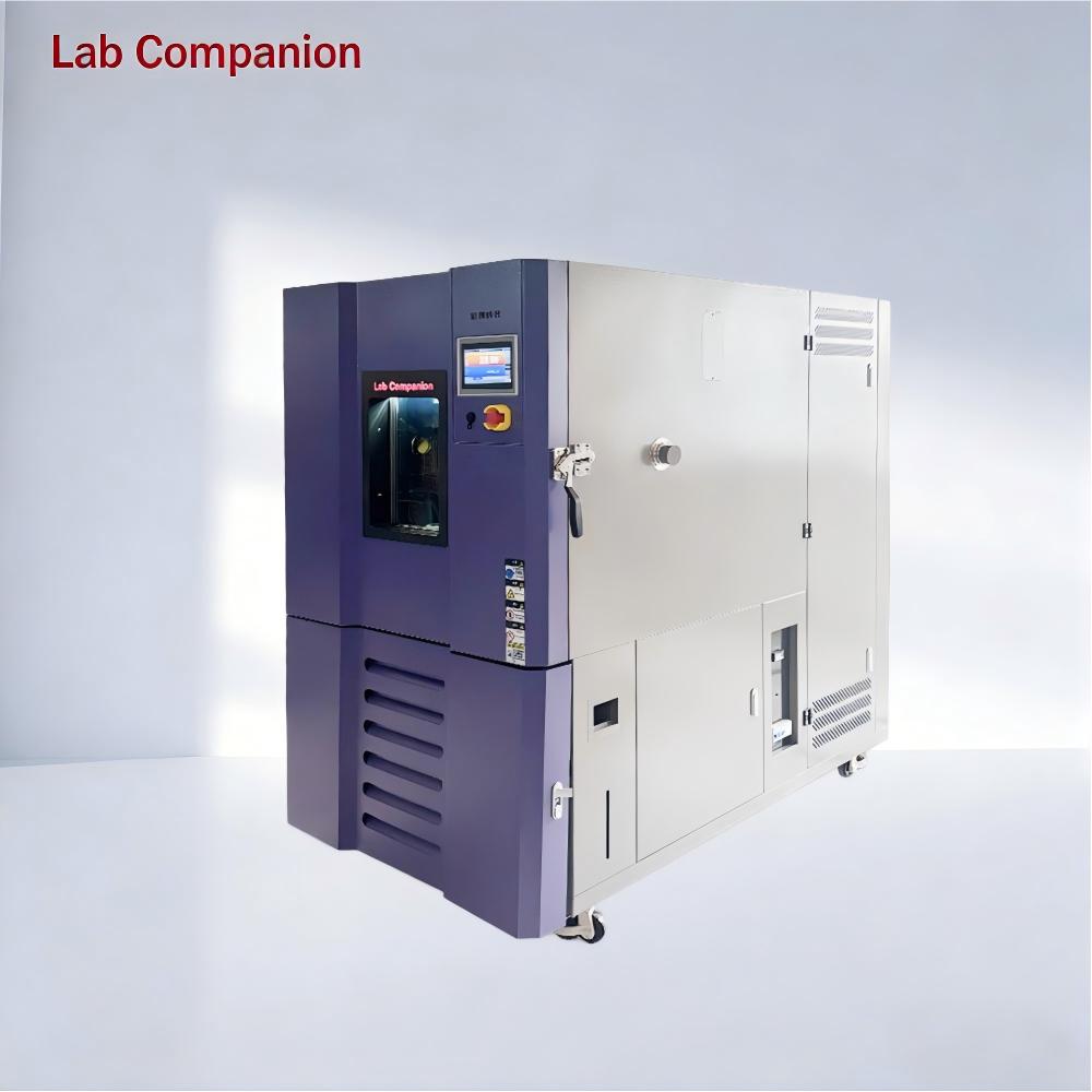
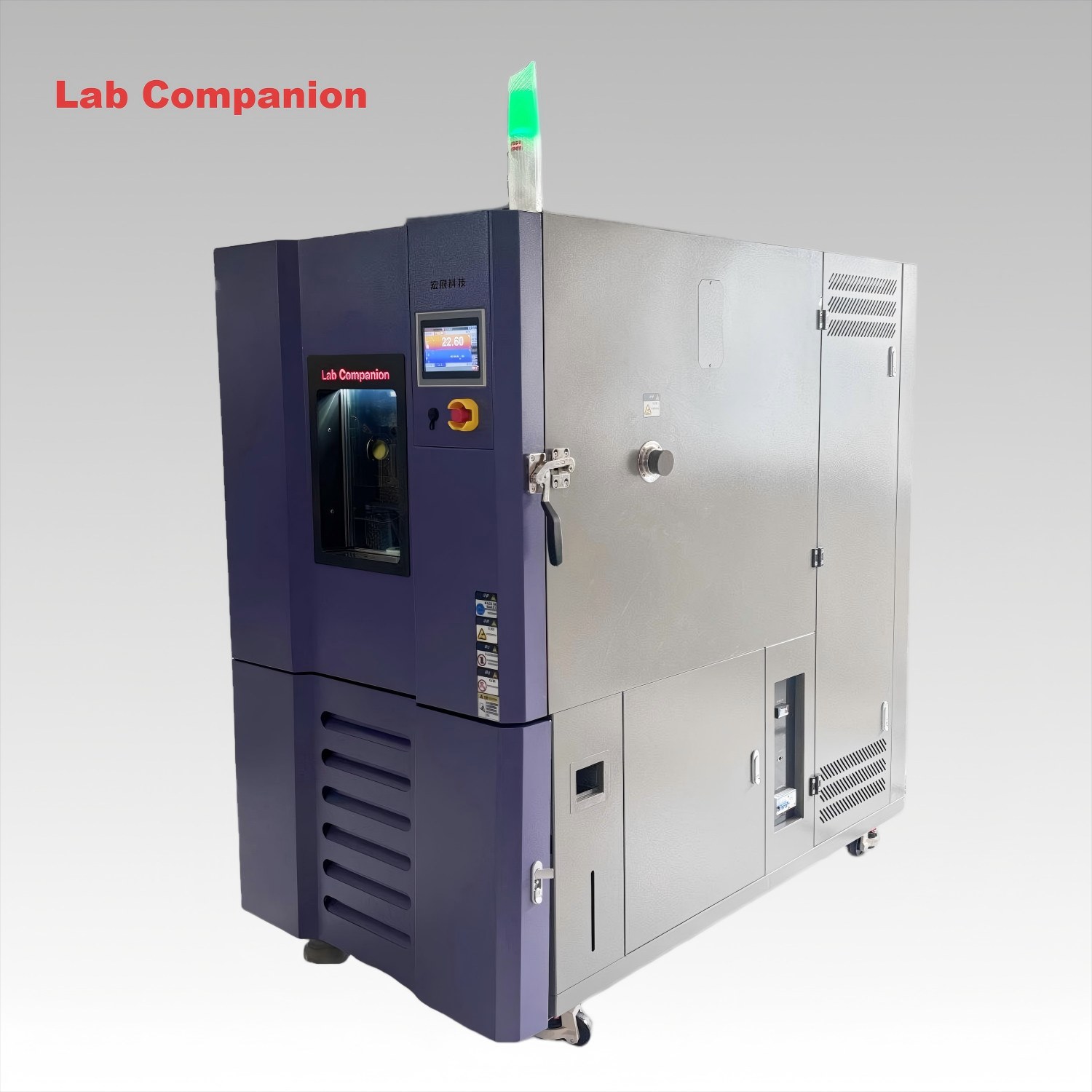
In the field of industrial product reliability testing, temperature test chambers are basic equipment, while rapid temperature change test chambers are upgraded models. Their core differences lie in performance, structure, application scenarios and cost. Below is a concise comparison from four core dimensions to clarify their positioning boundaries.
I. Core Performance: Essential Leap from "Steady-State Testing" to "Rapid Dynamic Simulation"
The core of performance differences lies in temperature change rate and control accuracy, which directly define testing capabilities. Standard temperature test chambers aim to meet basic steady-state testing, while Hongzhan's rapid models focus on precise simulation of extreme temperature-varying environments.
Standard chambers have a conventional temperature change rate of 0.7-1℃/min, with temperature fluctuation of ±0.5℃ and uniformity of ±2℃. They only comply with routine steady-state tests of GB/T 2423 series, suitable for basic temperature resistance verification in consumer electronics, home appliances and other industries, such as high-temperature aging of mobile phone chargers and low-temperature embrittlement tests of plastic toys.
Rapid temperature change chambers achieve performance leap, with customizable temperature change rate of 3-20℃/min (supporting linear heating/cooling), temperature fluctuation ≤±0.3℃, uniformity ≤±1.5℃, and no overshoot during temperature change. They can accurately simulate severe temperature variation and support accelerated aging tests. The standard temperature range is -70℃~+200℃, expandable to -80℃~+220℃ via customization, far exceeding standard models.
II. Structural Design: Differentiated Architecture Adapting to Performance Requirements
Structural design is the foundation of performance. Due to different testing objectives, the two models differ significantly in core component configuration and air duct design. Standard chambers adopt simplified structures to control costs, while Hongzhan's rapid models ensure stability under high-frequency temperature changes through precision architecture.
Standard models use a simple "single compressor + conventional air duct" structure, focusing on basic cooling/heating needs. With simple structure and few wearing parts, they are suitable for low-frequency, low-intensity tests. Single-stage refrigeration cycle is mostly used for low-temperature needs above -40℃, with relatively low refrigeration efficiency.
Hongzhan's rapid models are equipped with "dual-compressor cascade system + high-efficiency heat exchange module + impact-resistant structure". Core components include imported compressors (Bitzer, Copeland, etc.) and Swiss high-precision sensors, ensuring stable long-term high-frequency operation with MTBF over 8000 hours. They also support PLC programming and touch screen operation, with preset 100+ test programs for complex needs.
III. Application Scenarios: Precise Matching from "General Basic Testing" to "High-End Industry-Specific Needs"
Application differences stem from performance boundaries, forming a complementary pattern of "basic coverage" and "high-end breakthrough" to meet different industrial needs.
Standard models are suitable for consumer electronics, home appliances, toys and other industries, mainly for basic temperature resistance verification, applicable to general scenarios with low efficiency requirements and limited budget.
Hongzhan's rapid models focus on high-end industries such as new energy, automotive, aerospace and semiconductors, adapting to harsh tests like extreme temperature shock and high-frequency temperature fatigue. They support non-standard customization, such as explosion-proof devices and corrosion-resistant liners, to meet special industrial technical and environmental requirements.
IV. Full-Life Cycle Value and Operation & Maintenance Adaptability (Table Comparison)
Comparison Dimension
Standard Temperature Test Chamber
Rapid Temperature Change Test Chamber
Core Value
Stably complete basic temperature tests; suitable for simple-process, small-batch, long-cycle scenarios; meets basic quality inspection needs of small and medium-sized manufacturers
Improve test efficiency, quickly expose product defects, shorten R&D verification cycle; adapt to high-end enterprises' "fast R&D and iteration" rhythm, enabling efficiency-driven R&D
Operation Threshold
Simple structure and operation logic; ordinary operators can be competent after simple training
Intelligent operating system for easy basic operation; core functions require professionally trained personnel
Troubleshooting & Maintenance
Low difficulty in troubleshooting common faults; highly universal accessories; quick problem-solving to reduce downtime
Professional maintenance for core components; high stability and low fault rate; complete technical service system for rapid response
Suitable Enterprises
Small and medium-sized manufacturers with simple technical teams and basic testing needs
High-end manufacturers with professional technical teams and needs for continuous, high-precision testing
V. Summary: Core Selection Logic is "Demand Matching" Rather Than "Performance Stacking"
Standard temperature test chambers are "cost-effective choices" for basic tests with limited budget. Hongzhan's rapid models are "high-end customized choices" for extreme temperature simulation and high-efficiency precision testing. Essentially, they represent an upgrade from "meeting basic standards" to "breaking test boundaries". Selection should be based on industry standards, testing needs and budget, without blind pursuit of higher temperature change rate
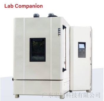
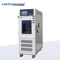
High and low temperature test chambers are the "invisible guardians" in industrial production and scientific research innovation. They can simulate extreme environments to test product reliability, from small mobile phone chips to large automotive components. Starting from basic cognition, core parameters, industry trends, and usage misunderstandings, this article interprets their value and Labcompanion's practice.
I. Basic Cognition: The "Environmental Tester" for Product Quality
High and low temperature test chambers simulate natural environments by artificially regulating temperature, exposing performance defects of products under extreme temperature conditions in advance, helping enterprises optimize designs before mass production and avoid recall risks. Their applications cover electronic and electrical, medical, automotive, scientific research institutions and other fields, with test objects including PCB boards, monitors, automotive sensors, etc.
II. Key Parameters: Core Indicators for Selecting the Right Equipment
Core parameters determine equipment adaptability, with key indicators as follows:
1. Temperature control accuracy (deviation ±0.1℃~±0.5℃, high precision suitable for scientific research/high-end manufacturing);
2. Temperature uniformity (high-quality equipment ≤±2℃, high-end models ≤±1℃);
3. . Temperature range (conventional -40℃~150℃, special scenarios up to -80℃~200℃+);
4. Temperature change rate (10℃/min+ rapid temperature change can shorten test cycles);
5. Volume (from dozens of liters of desktop to dozens of cubic meters of walk-in, suitable for different scenarios).
III. Industry Trends: Green, Intelligent and Customized as the Mainstream
With industry upgrading, three major trends highlight competitiveness: 1. Green energy saving: Adopting environmentally friendly refrigerants, optimized refrigeration cycle and other technologies, energy consumption can be reduced by 20%+; 2. Intelligent interconnection: Realizing remote monitoring, automatic data collection and analysis, suitable for digital management; 3. Customization: Providing personalized designs for medical sterility, new energy explosion-proof and other needs.
IV. Usage Misunderstandings: Four Major Pitfalls to Avoid
1. The temperature change rate is not the faster the better; it needs to match product characteristics and test standards;
2. Uniformity cannot be ignored; uneven temperature field will lead to result deviation; 3. Regular maintenance is indispensable, otherwise it will affect accuracy and increase energy consumption;
4. The load capacity should not exceed 30% of the chamber volume to avoid damaging temperature field uniformity.
V. Labcompanion: A Quality Practitioner Following Trends
Labcompanion focuses on R&D and practices the three major trends: In terms of green energy saving, it adopts environmentally friendly refrigerant R449A and cascade refrigeration + CO₂ working fluid technology, reducing energy consumption by 28%~38% and obtaining provincial energy-saving certification; In terms of intelligence, it is equipped with an AI intelligent control system, supporting remote monitoring and automatic data analysis, with preset 200+ test programs; In terms of customization, it provides customized temperature range, chamber structure, etc., covering the needs of various industries. Its equipment has excellent core parameters: temperature control accuracy ±0.1℃~±0.3℃, uniformity ≤±1.5℃, temperature range -80℃~200℃. Relying on 20 years of experience, it provides full-process services from demand analysis to maintenance.
High and low temperature test chambers bear the responsibility of ensuring product quality. Accurately understanding core information can help select equipment and avoid pitfalls. Labcompanion creates trend-compliant equipment through technological innovation, providing support for quality upgrading in various industries.
1. Electronics Industry (Chips, Components)
Q: Does inner tank size and material affect testing for small precision components?
A: Select 36-100L small-volume inner tank (reduces temperature fluctuation); prioritize 304 stainless steel (corrosion-resistant, uniform heat conduction). Confirm multi-point temperature collection (≥8 points) support. Hongzhan offers customizable zoned temperature measurement, synchronous data upload, and chip batch testing compatibility.
Q: Will the refrigeration system degrade after 72 hours of continuous high-intensity testing?
A: Focus on refrigeration configuration: choose two-stage cascade refrigeration (more stable than single-stage) with imported compressors (Danfoss/Coppa). Hongzhan equipment features MTBF of 20,000 hours, no continuous operation attenuation, and overload protection.
2. New Energy Industry (Batteries, Charging Piles)
Q: For battery testing with explosion-proof requirements, how to judge equipment explosion-proof rating and safety design?
A: Must comply with ATEX explosion-proof certification. Inner tank equipped with explosion-proof pressure relief valve and inert gas inlet; circuit adopts flameproof design. Hongzhan customizes Ex d IIB T4 explosion-proof test chambers, suitable for lithium battery thermal runaway simulation.
Q: Can equipment heating/cooling rate meet large-capacity battery pack testing? Is energy consumption high?
A: Select custom models ≥1000L with temperature change rate ≥10℃/min; adopt CO₂ natural refrigerant system (38% lower energy consumption than traditional). Hongzhan optimizes refrigeration circuits for new energy, maintaining stable rates under heavy loads and saving over 10,000 yuan in annual electricity costs.
3. Aerospace Industry (Components, Aircraft Assemblies)
Q: Can temperature uniformity meet standards in extreme temperature ranges (-80℃ to 200℃)?
A: Select equipment with "PID self-tuning + fuzzy control"; inner tank adopts honeycomb air duct design (reduces temperature difference). Hongzhan maintains uniformity ≤1.5℃ even at -80℃, passes GJB military standard certification, suitable for simulating extreme high-altitude environments.
Q: Can equipment connect to high-level data acquisition systems? Is data transmission stable?
A: Confirm RS485/Ethernet interface support, compatibility with LabVIEW/Excel, data sampling rate ≥1 time/second, and storage capacity ≥1 million records. Hongzhan equipment has electromagnetic shielding, ensuring interference-free transmission and seamless integration with aerospace research systems.
4. Medical Industry (Consumables, Devices)
Q: Medical consumables testing requires high inner tank cleanliness; what are the relevant equipment designs?
A: Inner tank made of 316L medical-grade stainless steel (sterilization efficiency ≥99%), with 120℃ automatic high-temperature sterilization; air duct designed with no dead corners (prevents dust accumulation). Hongzhan cleanroom test chambers comply with ISO 13485, suitable for syringe and medical sensor sterility testing.
Q: Test data needs 5+ years of traceability; do equipment storage and export functions meet requirements?
A: Must have audit trail, encrypted data storage for ≥5 years, one-click export to PDF/Excel, and tamper-proof design. Hongzhan equipment is equipped with industrial-grade storage modules, meeting FDA/CE regulatory requirements, facilitating medical device registration.
Industry-Specific Selection Core
Precise matching with industry-specific demands is key:
Electronics: Focus on precise temperature control and small-volume adaptation
New Energy: Prioritize explosion-proof, wide temperature range, and large-load capabilities
Aerospace: Emphasize extreme temperature resistance and high-level data connectivity
Medical: Highlight compliance, cleanliness, and data traceability
Avoid blind pursuit of uniform parameters; conduct targeted screening per industry standards (GJB, ISO 13485). Guangdong Hongzhan Technology Equipment provides industry-customized solutions, covering core technical requirements across fields. With professional certifications and compatible designs, it helps customers avoid selection pitfalls and achieve precise matching.
From the customer perspective, this guide sorts out core questions and selection criteria for high-low temp test chamber specs/performance across industries, with answers integrated with Hongzhan's advantages, fitting practical procurement scenarios.
Common Core Technical Spec Questions
1. How to choose temperature range? Is wider better?
Customer question: "Different industries have different temp requirements. Wide range or needs-based?"
Selection: Avoid blind pursuit of ultra-wide range (costly). Match industry needs: Electronics/Medical: -40℃~150℃ (basic); New Energy: -70℃~150℃ (extreme cold); Aerospace: -80℃~200℃ (extreme env). Hongzhan customizes -100℃~300℃ full range for cost-effectiveness.
2. How to choose temp change rate? Difference between "average" and "instantaneous"?
Customer question: "Rapid temp change needs 10℃/min. Average or instantaneous rate?"
Selection: Prioritize full-process average rate (actual test scenario fit). Electronics: 5-10℃/min sufficient; New Energy/Aerospace: ≥15-20℃/min. Hongzhan uses AI dynamic temp control + imported compressors, supporting 5-30℃/min adjustable with no instantaneous attenuation.
3. How to choose inner tank size? Conflict between load and temp uniformity?
Customer question: "Samples vary in size. Fixed or custom volume? Will uniformity drop when fully loaded?"
Selection: Volume matches single-test sample quantity (reserve 30% air duct space). Conventional: 36L (lab small-batch), 150L (industrial medium-batch), 500L+ (large samples). Prioritize custom tank brands. Hongzhan customizes 36L-10000L tanks with honeycomb air ducts, maintaining ≤1.5℃ uniformity even at full load.
4. Practical significance of temp accuracy/uniformity? How to verify?
Customer question: "Spec says ±0.5℃ accuracy. Achievable in use? Will deviation affect results?"
Selection: Accuracy determines data validity: Electronic chips: ≤±0.3℃; Medical devices: ≤±0.5℃; Uniformity: ≤1℃ (avoid local sample failure). Verification: Request 3rd-party calibration reports (e.g., NIM certification). Hongzhan equipment is calibrated before delivery, supporting on-site recheck.
5. How to judge humidity range/accuracy for humidity-heat models? Retrofit possible later?
Customer question: "Some tests need humidity. 0-98% RH or 40-95% RH? Retrofit humidity function later?"
Selection: General scenarios: 20-98% RH (±2% RH); Medical/Electronics: 5-98% RH (±1.5% RH, avoid low-humidity failure). Retrofit not recommended (air duct/control system modification risks stability); choose full-equipped models initially. Hongzhan humidity-heat models support 10-98% RH (ultrasonic humidification + condensation dehumidification) and offer pre-installed upgrade solutions for stability.
6. Upper limit for continuous operation? How to ensure stability long-term?
Customer question: "Need 100+ hours continuous test. Overload risk? Accuracy drop after 1 year?"
Selection: High-quality equipment has no mandatory limit; key is core component redundancy (e.g., dual-compressor backup). Confirm annual calibration and 1-year core component warranty. Hongzhan supports 7x24h operation (MTBF 20000h) with overload protection/high-temp alarm, free annual calibration, and ≤0.1℃ accuracy attenuation after 1 year.
Key selection tips: Match temp range, accuracy and uniformity to industry needs; reserve air duct space for tank size; prioritize humidity-heat function initially. Focus on continuous operation capability and core components; choose eco-friendly refrigerants. Hongzhan's customizable, precise, stable and eco-friendly equipment meets core spec demands, helping customers avoid pitfalls and select accurately.
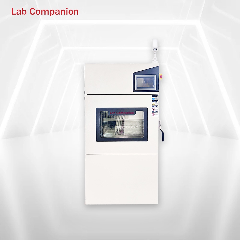
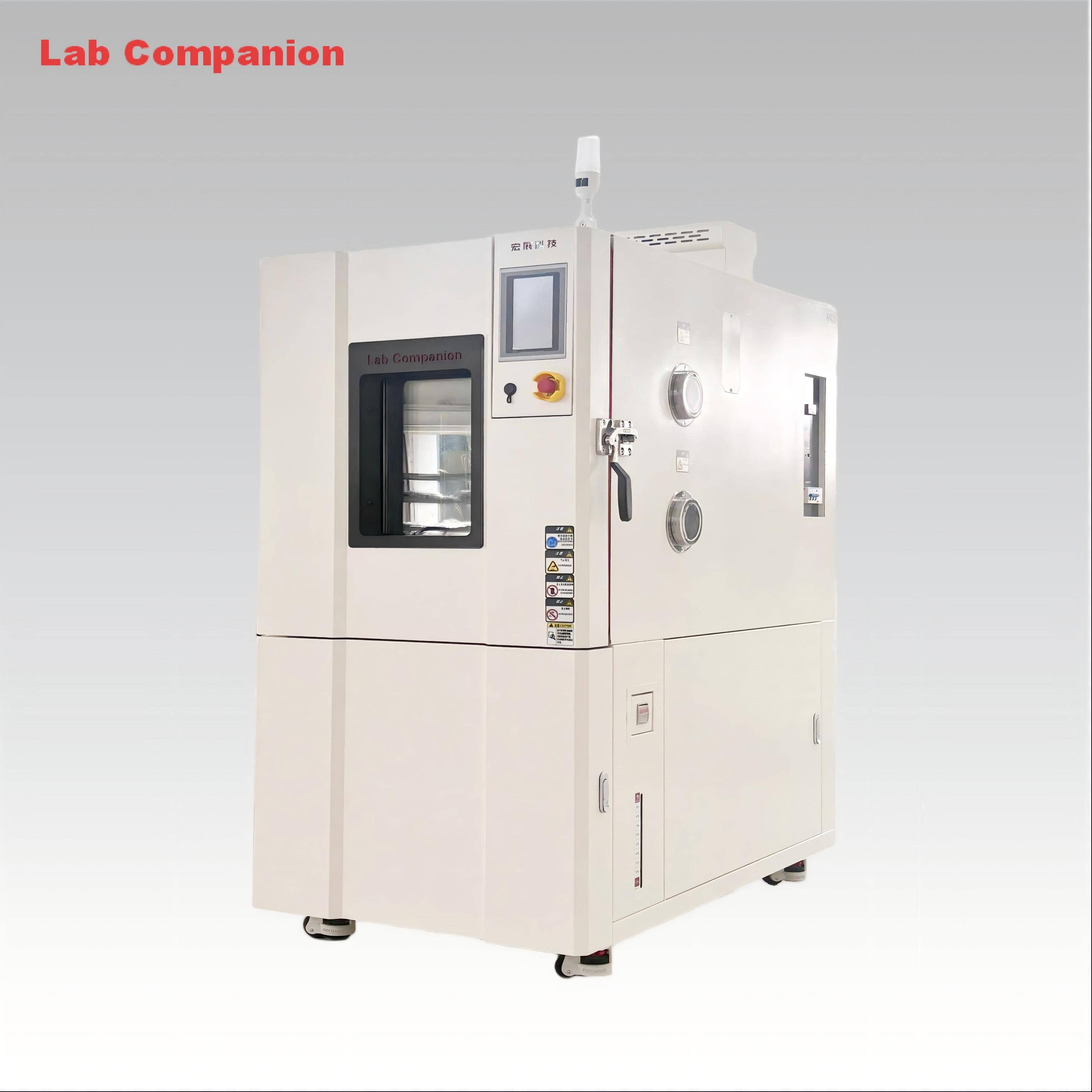
The glove-type high-low temperature test chamber is a key equipment for environmental reliability testing in electronics, automotive, aerospace and other fields. With the core advantages of "sealed isolation + precise temperature control + convenient operation", it has become an ideal solution for sample testing under extreme temperatures. Its core features can be summarized in the following six dimensions.
I. Wide-Range and Precise Temperature Control, Adapting to Diverse Testing Needs
The equipment has a wide temperature range. Conventional models can simulate extreme environments from -70℃ to +150℃, and customized models can expand the temperature range to adapt to high and low temperature resistance testing of various products. It adopts PT100 platinum resistance sensor and PID high-precision control algorithm, with temperature fluctuation ≤±0.5℃ and uniformity ≤±2.0℃, ensuring accurate test data; the heating rate is 1.0-3.5℃/min and the cooling rate is 0.7-1.2℃/min, which can quickly switch temperatures and improve test efficiency.
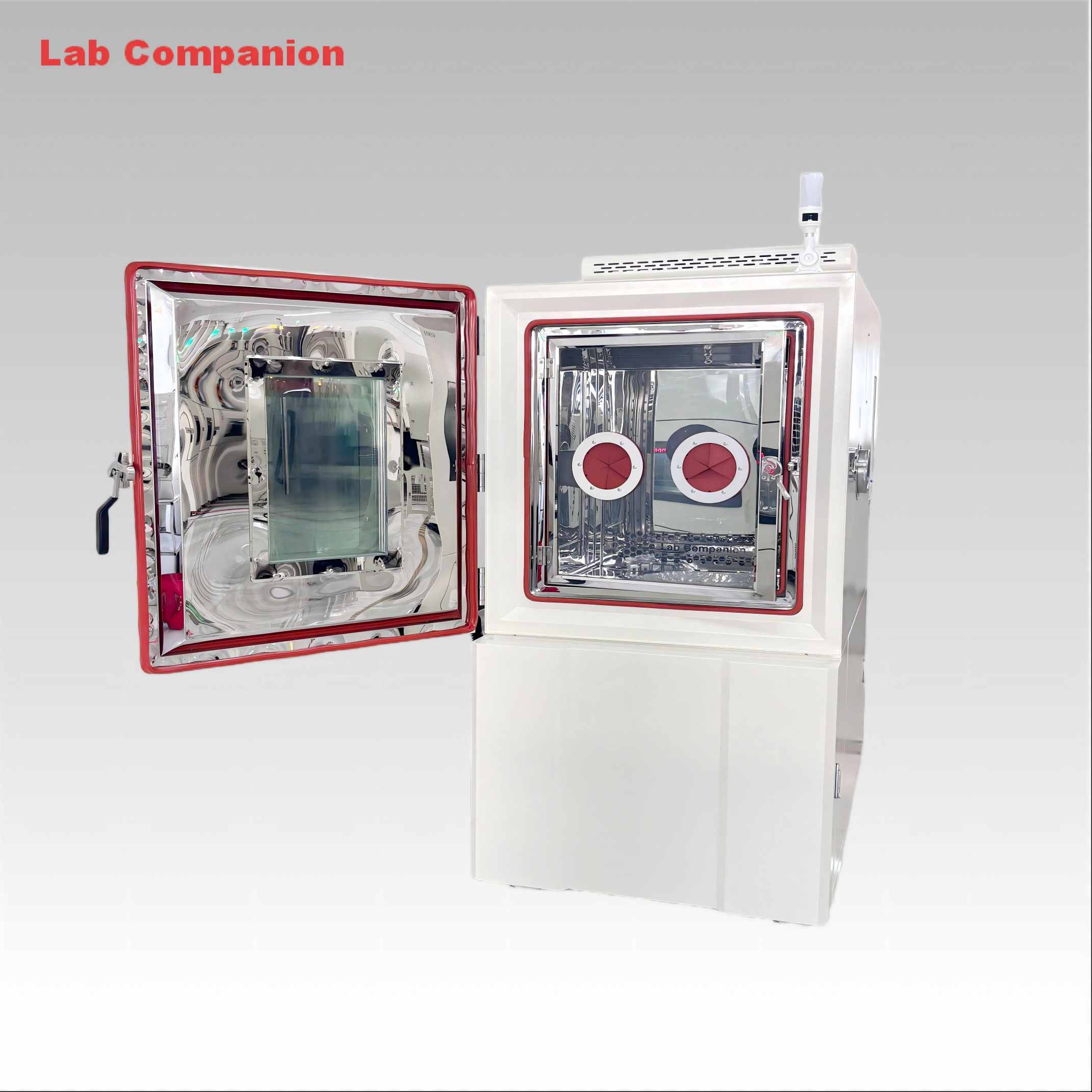
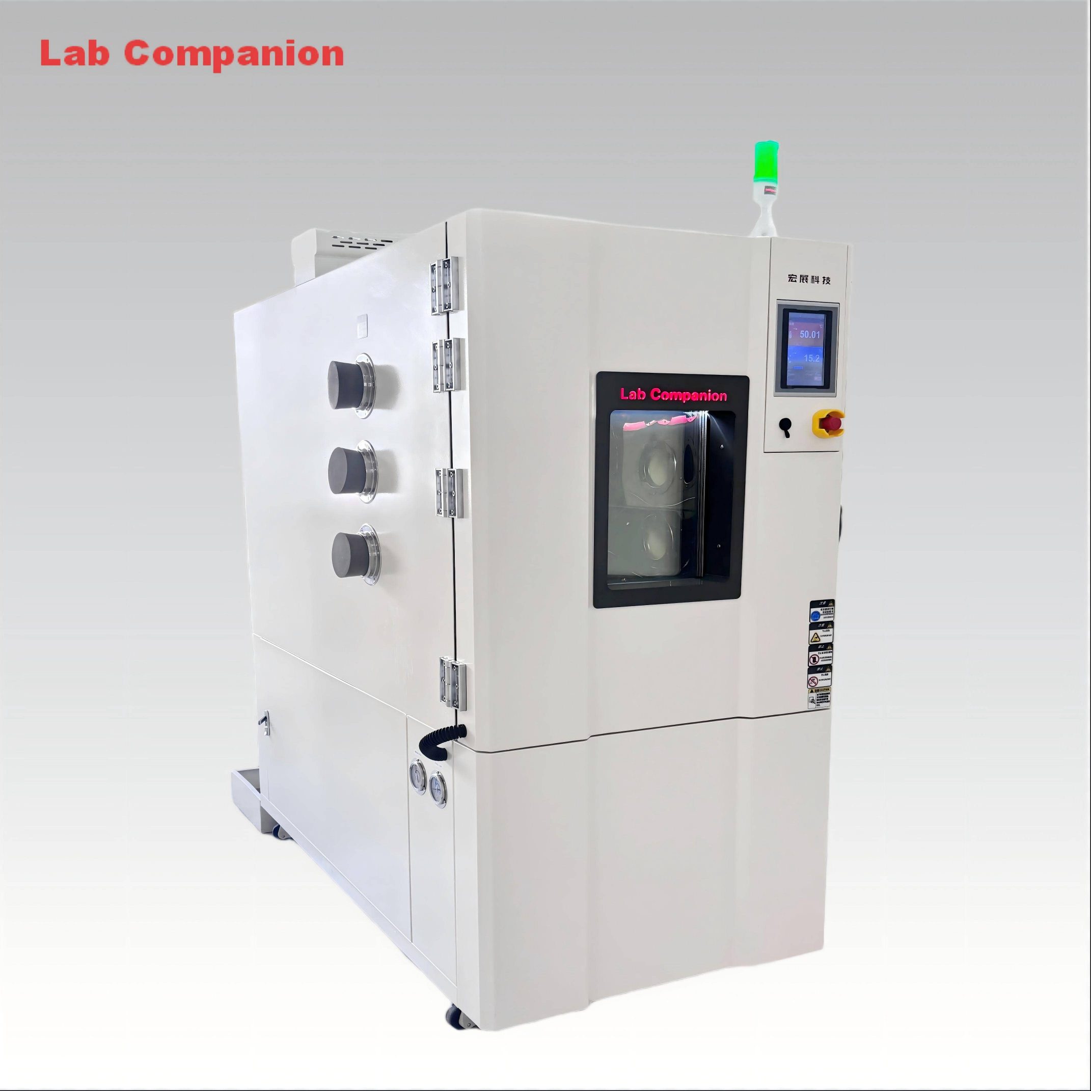
II. Sealed Glove Operation, Ensuring Test Continuity and Safety
The chamber is equipped with a sealed operation port and high-sealing silica gel gloves to form an isolated test environment. Operators can real-time complete sample testing, status observation and other operations through the gloves without interrupting the test, avoiding temperature and humidity fluctuations caused by opening and closing the door, and improving data reliability; at the same time, it blocks the impact of extreme temperature inside the chamber on the outside, prevents external impurities from entering, and ensures environmental cleanliness and operator safety.
III. Intelligent and Convenient Operation, Improving Test Efficiency
The equipment is equipped with a large-screen touch screen controller, supporting Chinese-English bilingual switching and intuitive operation. The controller can preset 100 groups of processes, 50 steps/group of test procedures, and support 250 cycles of testing, meeting the needs of alternating temperature testing; it is equipped with USB and network communication functions, which can real-time export data, print curves and remote monitoring operations, facilitating data traceability and management; some models are equipped with test holes, which can be connected to external power supplies to realize live sample testing and expand application scenarios.
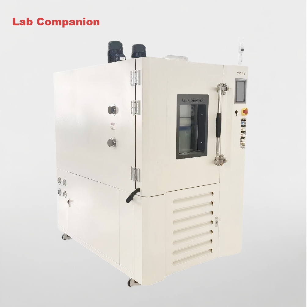
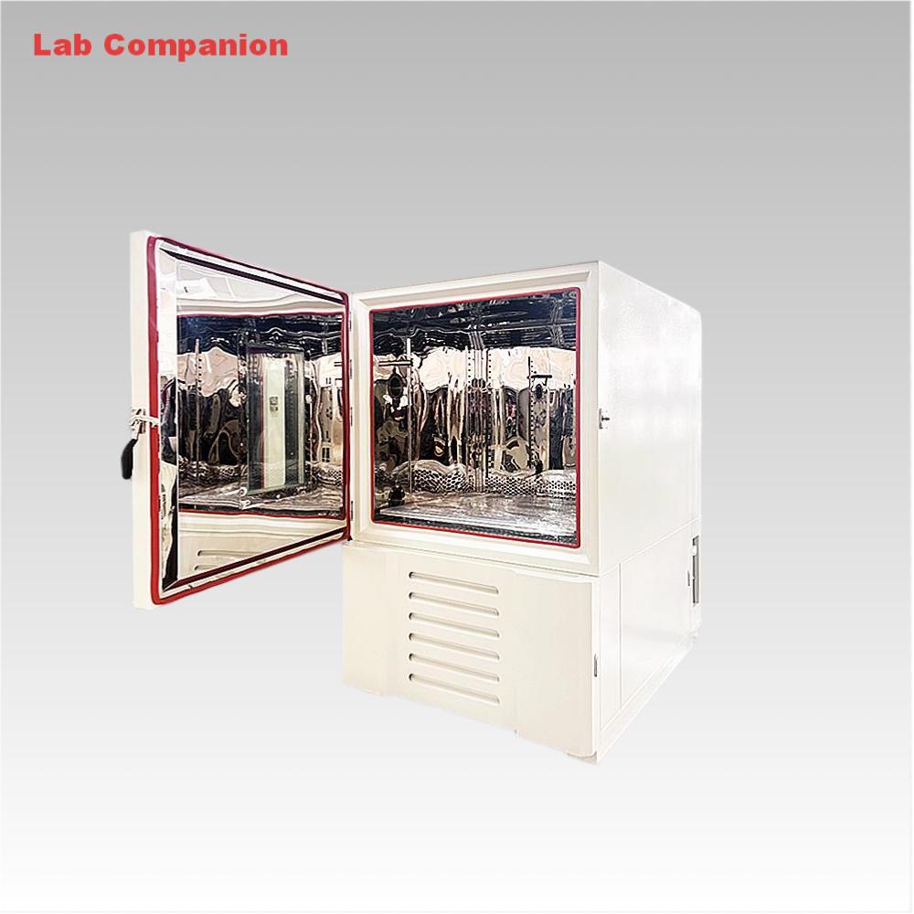
IV. Stable Structural Design, Ensuring Long-Term Stable Operation
The chamber adopts a double-layer composite structure. The outer shell is made of A3 steel plate with electrostatic spraying, which is corrosion-resistant and durable; the inner tank is made of SUS304 mirror stainless steel, which is high-temperature resistant and easy to clean; the middle is filled with 100mm high-density glass fiber cotton insulation layer, which is heat-insulating and energy-saving. The chamber door is equipped with double-layer high-temperature resistant sealing strips and hollow tempered glass observation window. The observation window is equipped with conductive film heating defrosting function, taking into account both sealing and observation needs. The refrigeration system adopts fully enclosed unit and environmentally friendly refrigerant, with forced air cooling, stable operation and low noise. It has passed 48-hour air pressure leak test to ensure stability and reliability.
V. Comprehensive Safety Protection, Reducing Test Risks
The equipment is built with multiple safety protection mechanisms, including over-temperature protection, refrigeration system overload and over-pressure protection, phase loss/phase reversal protection, leakage protection, water shortage protection, etc. It is equipped with three-color indicator lights to real-time display operation, standby and fault status. When a fault occurs, it will automatically shut down and prompt the cause, facilitating troubleshooting. The heating and refrigeration systems are independently designed to avoid interference, which not only improves temperature control accuracy, but also reduces the impact of single system failure on the test, ensuring equipment operation and sample safety.
VI. Compliance with Authoritative Standards, Adapting to Multi-Industry Needs
The product strictly complies with national and international standards such as GB/T2423.1-2008, GB/T2423.2-2008 and IEC60068. It is widely used in electronics, electrical engineering, automotive, aerospace, biomedicine, building materials and other fields. It can complete high and low temperature and constant temperature performance testing of materials and products, providing support for product design improvement and quality verification.
In summary, with the core advantages of precise temperature control, sealed operation, intelligence and convenience, and stability and reliability, the glove-type high-low temperature test chamber solves the pain points of dynamic testing under extreme temperatures. It is a key equipment for environmental reliability testing in multiple industries and provides solid guarantee for product quality improvement.
As a core environmental reliability testing equipment, the high-temperature test chamber evaluates the durability, stability and service life of materials, components and complete machines under high temperatures by simulating extreme environments. It is key to product R&D, quality inspection and certification. Its core value lies in replacing natural aging with controlled laboratory conditions, shortening test cycles, identifying potential defects accurately, and providing a scientific basis for quality optimization. Below is an analysis of its core features and main applications from a professional perspective.
I. Core Technical Features
The technical advantages of the high-temperature test chamber focus on three aspects: temperature control accuracy, environmental simulation authenticity and safety reliability, specifically as follows:
1. Precise Temperature Control and Uniformity: Adopting PID microcomputer automatic control algorithm with high-precision platinum resistance sensor, the temperature control accuracy reaches ±0.5℃, and the no-load internal temperature uniformity is within ±1.0℃. The forced air circulation system (high-temperature resistant motor + multi-wing wind wheel) enables rapid heat diffusion, avoiding local temperature differences affecting test results.
2. Efficient Heating and Energy-Saving Insulation: Equipped with honeycomb stainless steel heating tubes for fast heating, high thermal stability and long service life. The chamber uses SUS#304 stainless steel inner lining and high-density imported rock wool insulation, combined with heat-resistant and corrosion-resistant silicone seals, effectively reducing heat loss, lowering energy consumption and ensuring high-temperature stability.
3. Intelligent Operation and Data Traceability: Supports custom temperature curves for complex processes such as step heating and constant temperature maintenance. High-end models integrate multi-parameter monitoring modules to synchronize temperature and voltage data; some are equipped with image recognition systems for automatic sample aging analysis, reducing human error.
4. Comprehensive Safety Protection: Built-in over-temperature protection, overload power-off and electric heating over-current protection. It automatically cuts off heating power and alarms when temperature exceeds the set range, with explosion-proof door locks and other structural designs ensuring test safety and reliability.
II. Main Application Fields
The high-temperature test chamber is widely used in high-end manufacturing and scientific research fields such as electronics, automotive and aerospace, mainly serving product reliability verification needs:
1. Electronic and Electrical Industry: Used for high-temperature aging testing of chips, capacitors and resistors to evaluate performance attenuation. Conducts high-temperature operation tests on PCBs, mobile phones and servers to verify functional stability under extreme temperatures and troubleshoot loose welds and short circuits.
2. Automotive Industry: Simulates summer in-vehicle high temperatures for durability testing of on-board electronics (control units, sensors, displays) in engine compartments. Tests heat resistance and weather resistance of automotive interior materials and external coatings to ensure vehicle reliability in extreme climates.
3. Aerospace and Military Industry: Simulates high-altitude aerodynamic heating or ground high temperatures to test the high-temperature stability of aircraft components, electronics and spacecraft thermal insulation materials. Verifies military equipment reliability under extreme high temperatures per national military standards, avoiding high-temperature-induced structural cracking and performance failure.
4. New Energy and Photovoltaic Field: Performs high-temperature charge-discharge and storage safety tests on lithium battery modules and solar inverters. Simulates desert high temperatures per IEC 61215 to evaluate solar panel efficiency attenuation and ensure long-term outdoor stability.
5. Pharmaceutical and Material Research: Tests the stability and degradation rate of drugs and vaccines under high temperatures to determine transportation and storage shelf life. Evaluates high-temperature performance of new plastics, composites and architectural coatings, analyzing thermal stability and strength changes to support material selection and R&D.
III. Summary
With precise environmental simulation and comprehensive reliability verification capabilities, the high-temperature test chamber is a core component of modern industrial quality control systems. Its development trend is towards multi-environment collaborative simulation (high temperature + humidity + vibration) and intelligent data analysis, which will further improve test efficiency and accuracy, providing stronger support for high-end product R&D and quality assurance across industries.
1. Core Test Purpose
The composite salt spray test chamber centers on simulating salt spray corrosion environments, with optional integration of temperature and humidity conditions. It is mainly used to test the corrosion resistance of materials, components and finished products, especially for evaluating the durability of coating/plating protection systems and the reliability of products in marine or high-salt industrial environments.
The high-low temperature test chamber focuses on simulating extreme temperature and temperature change environments. Its core goal is to verify products’ temperature resistance, structural stability and performance consistency under high/low temperature and temperature cycle conditions, such as testing the working status of electronic components, thermal expansion/contraction resistance of metal parts, and temperature-induced aging of plastic components.
2.Test Environment Composition
The core environmental medium of the composite salt spray test chamber is salt spray (typically formed by atomizing 5% sodium chloride solution). It can achieve cyclic composite environments including salt spray, constant temperature and humidity, and drying stages. Some models also control key parameters like salt spray deposition rate and spray pressure, with the overall environment built around "corrosion triggers".
The high-low temperature test chamber’s core is temperature (covering -70℃~150℃ or a wider range). Some models integrate humidity control (high-low temperature and humidity test chambers). It precisely regulates internal temperature and humidity via compressors, heaters, humidifiers and other components, without salt spray-related media or systems.
3.Applicable Test Objects & Industries
The composite salt spray test chamber is mainly for products requiring corrosion protection such as auto parts, hardware electroplated parts, marine engineering equipment, outdoor communication devices, and aerospace fasteners. It is widely used in automotive, shipbuilding, hardware, and electronic protection industries.
The high-low temperature test chamber has a broader scope, covering all products that need temperature adaptability verification, including electronic appliances, semiconductor components, new energy batteries, instruments, military equipment, and household appliances. It is a basic environmental testing device for electronics, new energy, military, and consumer electronics industries.
4. Core Technical Structure
The composite salt spray test chamber is equipped with a salt spray generation system (spray tower, brine tank, nozzle) and corrosion fluid recovery/neutralization devices. Its chamber body requires high corrosion resistance (usually made of PVC, PP or special stainless steel) to prevent self-corrosion by salt spray.
The high-low temperature test chamber’s core is a temperature control system (compressor, condenser, evaporator, heater). Models with humidity function include humidification and dehumidification modules. The chamber focuses on thermal insulation (with polyurethane foam insulation layer) and has no special corrosion-resistant design.
5.Test Evaluation Indicators
Key evaluation indicators for composite salt spray tests are corrosion levels, such as blistering/peeling area of coatings, rust grade of base metals, and the correlation between test duration and corrosion failure time.
Evaluation indicators for high-low temperature tests focus on product performance and structural changes, including functional normality under extreme temperatures, parameter drift range, deformation/cracking of structural parts, and mechanical property attenuation of materials.
Test chambers, as core equipment for environmental reliability testing across industries such as electronics, automotive, aerospace, and new energy, rely on a multi-dimensional, redundant safety protection system to ensure long-term operational stability, personnel safety, and the integrity of test samples and equipment. Beyond basic safety guarantees, these protection mechanisms are designed to adapt to complex test scenarios and extreme environmental conditions. Here’s a professional and detailed breakdown of the core protection settings:
1. Refrigeration System Protection
Compressor protection: Equipped with overpressure, overheating, and overcurrent triple protection mechanisms. Real-time monitoring of operating pressure, exhaust temperature, and working current prevents compressor burnout, cylinder scuffing, or seal damage caused by abnormal conditions such as refrigerant leakage, pipeline blockage, or voltage fluctuations.
Refrigerant protection: Integrated high/low pressure switches and overload protection devices continuously monitor the refrigerant circulation system. When pressure exceeds the safe threshold or the system is overloaded, the device automatically cuts off the corresponding circuit and triggers an alarm, ensuring stable refrigerant flow and avoiding system damage due to pressure anomalies.
2. Test Area Protection
Multi-layer over-temperature protection (redundant design):
1st layer: Adjustable high/low temperature over-temperature protection, dynamically linked to the set operating control temperature. When the test area temperature deviates from the set range by a preset value, the system automatically adjusts the heating/cooling module or pauses operation to prevent sample damage.
2nd/3rd layers: Independent electronic high-temperature over-temperature protection devices (double redundancy). Directly connected to the power supply circuit, these devices bypass the main control system to cut off power immediately if the 1st layer protection fails, eliminating potential fire hazards or equipment damage caused by excessive temperature.
Fan motor overcurrent protection: Monitors the operating current of the test area circulation fan. If the motor jams, wears, or experiences current surges due to other faults, the protection system triggers an alarm and cuts off power to avoid motor burnout and ensure uniform temperature distribution in the test chamber.
Fault alarm system: Integrates sound and light alarms with a digital display. When abnormalities occur (e.g., over-temperature, water shortage, or sensor failure), the system immediately cuts off the relevant power supply, activates the alarm, and displays the specific fault cause on the control panel for quick troubleshooting.
Active water shortage reminder: For humidity-controlled test chambers, a real-time water level monitoring sensor in the humidity water tank triggers an audible and visual alarm when the water level is too low. The system pauses the humidity control function to prevent dry burning of the humidifier and ensure the stability of the humidity control system.
Dynamic high/low temperature protection: Real-time adapts to the set test parameters (temperature range, rate of change). During rapid temperature rise/fall or extreme temperature tests, the protection system dynamically adjusts the safety threshold to avoid false triggers while ensuring comprehensive protection against temperature anomalies.
3. General Electrical Protection
Main power supply protection: Equipped with phase sequence and phase loss protection devices. Automatically detects the phase sequence and integrity of the three-phase power supply; if phase sequence reversal or phase loss occurs, the system locks the power supply and alarms to prevent damage to the compressor, fan, and other core components caused by incorrect power supply.
Short circuit & leakage/surge protection: Configured with high-sensitivity short circuit breakers to quickly cut off power in case of line short circuits, avoiding electrical fires or component burnout. Equipped with leakage circuit breakers and RC electronic surge protectors to prevent electric shock hazards caused by equipment leakage and suppress voltage surges from the power grid, protecting the control system and electronic components.
Sensor self-detection: Real-time self-inspection of temperature, humidity, and other key sensors. If a sensor malfunctions (e.g., signal loss, inaccurate measurement), the system immediately alarms and switches to backup sensor data (if equipped) or pauses operation to ensure the reliability of test data and prevent misoperation due to false sensor signals.
Dry heating protection (humidity water circuit): For the humidity water circuit and humidifier, a dedicated dry heating protection device monitors the water level and heating status. If the humidifier heats without water, the protection system cuts off the heating power immediately to avoid humidifier burnout and extend the service life of the humidity system.
Expandable protection: Reserved 2 fault detection input interfaces, supporting customized addition of special protection modules (e.g., gas leakage protection for flammable/explosive test samples, pressure protection for sealed test chambers) to meet the safety requirements of industry-specific test scenarios.
These multi-layered, redundant, and configurable protection mechanisms form a comprehensive safety barrier for test chambers. Whether in routine reliability testing or extreme environmental simulations, they ensure the equipment operates stably and reliably, while maximally safeguarding the safety of operators, test samples, and the equipment itself—becoming a key guarantee for the accuracy of test results and long-term operational efficiency.
For enterprises in manufacturing, electronic technology, and related industries, product reliability testing is a critical quality assurance link. However, the operational costs of environmental test chambers—core testing equipment—are often overlooked. Many businesses focus solely on testing precision during procurement, only to be troubled by high energy bills in long-term use. Our energy-saving environmental test chamber effectively resolves the conflict between "accurate testing" and "cost control," providing comprehensive support for product lifecycle cost management.
Core Energy-Saving Feature: Intelligent Refrigeration System Regulation
As the primary energy-consuming component of environmental test chambers, the energy regulation technology of the refrigeration system directly determines the equipment’s energy efficiency. On the premise of meeting core technical indicators, this test chamber innovatively integrates multiple energy adjustment measures to achieve intelligent dynamic control of refrigeration capacity.
The system precisely regulates evaporation temperature via the controller and links it with a hot gas bypass energy adjustment mechanism, matching refrigeration demand in real time based on the required cooling rate and target temperature range. When approaching the set low temperature, the system automatically reduces refrigeration capacity to avoid temperature overshoot—a common issue in traditional models—ensuring test stability. During the constant temperature phase, it abandons the energy-intensive "hot-cold balance" mode, optimizing energy utilization at the source. Verified in real operating conditions, the energy-saving effect reaches up to 30%, significantly reducing long-term operational costs, especially for enterprises requiring 24/7 continuous operation.
Precision & Energy Efficiency: Optimized Heating System Power Control
Refined control of the heating system further enhances the equipment’s energy-saving advantages and temperature control precision. The system adopts a synergistic control scheme of temperature controllers and thyristors: the temperature controller collects real-time temperature signals and issues control commands, while thyristors precisely adjust the heater’s power output.
When the temperature is far below the set value, thyristors deliver full power for rapid heating. As the temperature gradually approaches the set value, the output power decreases incrementally; once the target temperature is reached, power output stops immediately. This on-demand power distribution mode eliminates energy waste and ensures precise temperature control, providing a stable and reliable temperature environment for tests.
For example: When the internal temperature is significantly lower than the set value, thyristors operate at full power, and the heater runs at maximum load to ensure rapid temperature rise. As the temperature nears the target, the thyristor’s output power gradually decreases. Once the target temperature is achieved, the thyristor stops power output immediately, and the heater enters standby mode. This "on-demand power supply" mode eliminates the drawback of "frequent start-stop" in traditional heating systems—avoiding ineffective energy consumption while greatly improving temperature control precision, making it particularly suitable for test scenarios requiring high temperature stability.
Dual-System Synergy: Safeguard Enterprise Costs
From the refrigeration system’s intelligent energy adjustment to the heating system’s precision power control, our environmental test chamber centers on dual-system collaborative energy-saving technology. While ensuring accurate test data, it maximizes energy cost reduction. Choosing our test chamber not only guarantees product testing quality but also enables scientific management of enterprise operational costs, providing peace of mind throughout your product R&D and production processes.
In addition, if your enterprise is seeking a cost-effective environmental test chamber or struggling with high energy consumption from existing equipment, we recommend focusing on our energy-saving model. Let professional equipment protect your product quality while reducing costs and enhancing efficiency for your business.


 एक कहावत कहना


 IPv6 नेटवर्क समर्थित